UML is popular for its diagrammatic notations. We all know that UML is for visualizing, specifying, constructing and documenting the components of software and non software systems. Here theVisualization is the most important part which needs to be understood and remembered by heart.
Structural Things:
Graphical notations used in structural things are the most widely used in UML. These are considered as the nouns of UML models. Following are the list of structural things.
- Classes
- Interface
- Collaboration
- Use case
- Active classes
- Components
- Nodes
Class Notation:
UML class is represented by the diagram shown below. The diagram is divided into four parts.
- The top section is used to name the class.
- The second one is used to show the attributes of the class.
- The third section is used to describe the operations performed by the class.
- The fourth section is optional to show any additional components.
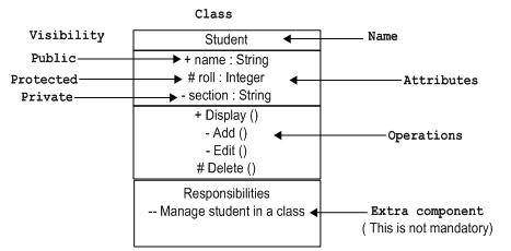
Classes are used to represent objects. Objects can be anything having properties and responsibility.
Object Notation:
The object is represented in the same way as the class. The only difference is the name which is underlined as shown below.
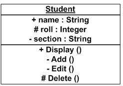
As object is the actual implementation of a class which is known as the instance of a class. So it has the same usage as the class.
Interface Notation:
Interface is represented by a circle as shown below. It has a name which is generally written below the circle.
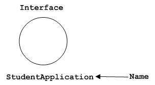
Interface is used to describe functionality without implementation. Interface is the just like a template where you define different functions not the implementation. When a class implements the interface it also implements the functionality as per the requirement.
Collaboration Notation:
Collaboration is represented by a dotted eclipse as shown below. It has a name written inside the eclipse.
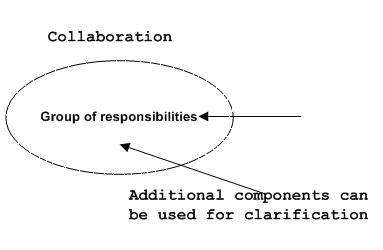
Collaboration represents responsibilities. Generally responsibilities are in a group.
Use case Notation:
Use case is represented as an eclipse with a name inside it. It may contain additional responsibilities.
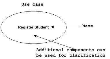
Use case is used to capture high level functionalities of a system.
Actor Notation:
An actor can be defined as some internal or external entity that interacts with the system.
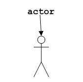
Actor is used in a use case diagram to describe the internal or external entities.
Initial State Notation:
Initial state is defined to show the start of a process. This notation is used in almost all diagrams.
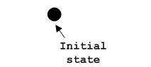
The usage of Initial State Notation is to show the starting point of a process.
Final State Notation:
Final state is used to show the end of a process. This notation is also used in almost all diagrams to describe the end.
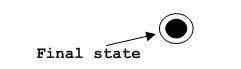
The usage of Final State Notation is to show the termination point of a process.
Active class Notation:
Active class looks similar to a class with a solid border. Active class is generally used to describe concurrent behaviour of a system.
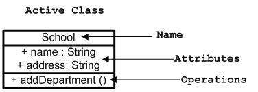
Active class is used to represent concurrency in a system.
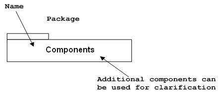
Component Notation:
A component in UML is shown as below with a name inside. Additional elements can be added wherever required.
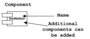
Component is used to represent any part of a system for which UML diagrams are made.
Node Notation:
A node in UML is represented by a square box as shown below with a name. A node represents a physical component of the system.
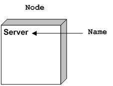
Node is used to represent physical part of a system like server, network etc.
Behavioural Things:
Dynamic parts are one of the most important elements in UML. UML has a set of powerful features to represent the dynamic part of software and non software systems. These features include interactions and state machines.
Interactions can be of two types:
- Sequential (Represented by sequence diagram)
- Collaborative (Represented by collaboration diagram)
Interaction Notation:
Interaction is basically message exchange between two UML components. The following diagram represents different notations used in an interaction.
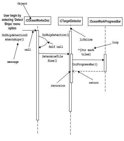
Interaction is used to represent communication among the components of a system.
Grouping Things:
Organizing the UML models are one of the most important aspects of the design. In UML there is only one element available for grouping and that is package.
Package Notation:
Package notation is shown below and this is used to wrap the components of a system.
Annotational Things:
In any diagram explanation of different elements and their functionalities are very important. So UML has notes notation to support this requirement.
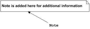
Note Notation:
This notation is shown below and they are used to provide necessary information of a system.
Relationships
A model is not complete unless the relationships between elements are described properly. TheRelationship gives a proper meaning to an UML model. Following are the different types of relationships available in UML.
- Dependency
- Association
- Generalization
- Extensibility
Dependency Notation:
Dependency is an important aspect in UML elements. It describes the dependent elements and the direction of dependency.
Dependency is represented by a dotted arrow as shown below. The arrow head represents the independent element and the other end the dependent element.
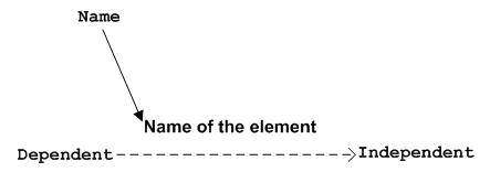
Dependency is used to represent dependency between two elements of a system.
Association Notation:
Association describes how the elements in an UML diagram are associated. In simple word it describes how many elements are taking part in an interaction.
Association is represented by a dotted line with (without) arrows on both sides. The two ends represent two associated elements as shown below. The multiplicity is also mentioned at the ends (1, * etc) to show how many objects are associated.
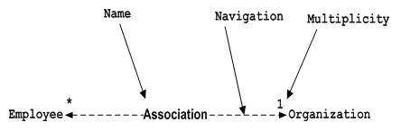
Association is used to represent the relationship between two elements of a system.
Generalization Notation:
Generalization describes the inheritance relationship of the object oriented world. It is parent and child relationship.
Generalization is represented by an arrow with hollow arrow head as shown below. One end represents the parent element and the other end child element.
Generalization is used to describe parent-child relationship of two elements of a system.
Extensibility Notation:
All the languages (programming or modeling) have some mechanism to extend its capabilities like syntax, semantics etc. UML is also having the following mechanisms to provide extensibility features.
- Stereotypes (Represents new elements)
- Tagged values (Represents new attributes)
- Constraints (Represents the boundaries)
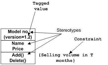
Extensibility notations are used to enhance the power of the language. It is basically additional elements used to represent some extra behaviour of the system. These extra behaviours are not covered by the standard available notations.
More details are found here
I found this information here, a great blog to follow